LXW26 Series Universal Rotary Switch
LXW26 series universal rotary switch is mainly used in electric circuit of AC50Hz,rated work voltage being 440V or below, DC voltage 240V or below and rated current from 20A to 160A. It is for controlling manually non-frequent switch-on and off circuit, additionally. it also could directly control three-phase asynchronous motor and be used for controlling and measuring circuit. Lt has a wide using range, so it can replace every rotary switch such as circuit
control switch, test equipment's switch, motor-control and master control switch, etc.LXW26 series rotary switches comply with: GB 14048.3, GB 14048.5, and IEC 60947-5-1. Among which, the LXW26-10, LXW26-16, LXW26-20 and LXW26-25 enjoy the fingerproof terminals, which offered an extra advantage.1) Position style; 2) Auto-return style; 3) Position & Auto-rerurn style
Advantages and Applications
Product advantages:
1. Versatility: The LW26 switch is designed to handle a variety of electrical circuits, making it suitable for different applications.
2. Reliable performance: It is built with high-quality materials and undergoes rigorous testing to ensure long-lasting and reliable performance.
3. Easy installation: The switch is designed for easy installation, with clear labeling and user-friendly instructions.
4. Safety features: It incorporates safety mechanisms such as arc extinguishing chambers and insulation barriers to protect against electrical hazards.
5. Durability: The LW26 switch is built to withstand harsh environments and has a long operational life.
Applications:
1. Industrial machinery: The LW26 switch is commonly used in industrial machinery for controlling power supply, motor direction, and circuit switching.
2. Electrical distribution: It is suitable for use in electrical distribution systems to control the flow of electricity and switch between power sources.
3. Automation systems: The switch can be integrated into automation systems to control various functions and processes.
4. Building automation: It is used in building automation systems for controlling lighting, HVAC systems, and other electrical equipment.
5. Power generation: The LW26 switch is also used in power generation facilities for controlling generator circuits and power transfer.
Diagram for the operation and position of handle
| Operation Angle | Code | Position of Handle |
| 30° Rotation | 45° Rotation | 60° Rotation | 90° Rotation |
| Spring Return | A |
|
|
|
|
| 0° | ←30° |
|
|
|
|
|
|
|
| 0° | ←45° |
|
|
|
|
|
|
|
|
|
|
|
|
|
| B |
|
|
|
| 30°→ | 0° | ←30° |
|
|
|
|
|
|
| 45°→ | 0° | ←45° |
|
|
|
|
|
|
|
|
|
|
|
|
|
| Limited Movement | C |
|
|
|
|
| 0° | 30° |
|
|
|
|
|
|
|
| 0° | 45° |
|
|
|
|
| 0° | 60° |
|
| 0° | 90° |
|
| D |
|
|
|
| 30° | 0° | 30° |
|
|
|
|
|
|
| 45° | 0° | 45° |
|
|
|
| 60° | 0° | 60° |
| 90° | 0° | 90° |
|
| E |
|
|
|
| 30° | 0° | 30° | 60° |
|
|
|
|
|
| 45° | 0° | 45° | 90° |
|
|
| 90° | 30° | 30° | 90° |
| 90° | 0° | 90° | 180° |
| F |
|
|
| 60° | 30° | 0° | 30° | 60° |
|
|
|
|
| 90° | 45° | 0° | 45° | 90° | 135° |
|
| 90° | 30° | 30° | 90° | 150° |
|
|
|
|
| G |
|
|
| 60° | 30° | 0° | 30° | 60° | 90° |
|
|
| 135° | 90° | 45° | 0° | 45° | 90° | 135° |
| 150° | 90° | 30° | 30° | 90° | 150° |
|
|
|
|
| H |
|
| 90° | 60° | 30° | 0° | 30° | 60° | 90° |
|
|
| 135° | 90° | 45° | 0° | 45° | 90° | 135° | 180° |
|
|
|
|
|
|
|
|
|
|
| I |
|
| 90° | 60° | 30° | 0° | 30° | 60° | 90° | 120° |
|
|
|
|
|
|
|
|
|
|
|
|
|
|
|
|
|
|
|
|
| J |
| 120° | 90° | 60° | 30° | 0° | 30° | 60° | 90° | 120° |
|
|
|
|
|
|
|
|
|
|
|
|
|
|
|
|
|
|
|
|
| K |
| 120° | 90° | 60° | 30° | 0° | 30° | 60° | 90° | 120° | 150° |
|
|
|
|
|
|
|
|
|
|
|
|
|
|
|
|
|
|
|
| L | 150° | 120° | 90° | 60° | 30° | 0° | 30° | 60° | 90° | 120° | 150° |
|
|
|
|
|
|
|
|
|
|
|
|
|
|
|
|
|
|
|
| M | 150° | 120° | 90° | 60° | 30° | 0° | 30° | 60° | 90° | 120° | 150° | 180° |
|
|
|
|
|
|
|
|
|
|
|
|
|
|
|
|
|
|
| N |
|
|
|
|
|
|
|
|
|
|
|
|
|
| 45° |
| 45° |
|
|
|
|
| 30° | 30° |
|
|
|
|
|
|
| Limited Movemen | Z |
|
|
|
| 30°→ | 0° | 60° |
|
|
|
|
|
|
| 90° | 0 | ←45° |
|
|
|
|
|
|
|
|
|
|
|
|
|
| & Spring Return |
|
|
|
|
|
|
|
|
|
|
|
|
| 135° | ←90° | 0° | ←45° |
|
|
|
|
|
|
|
|
|
|
|
|
|
Classification
| Classified by utilization | Classified by operation | Classified by contact system |
| Change-over switch | Limited movement | Switches with limited movement could have 12 layers in maximum (for 32A and below), and for 63A and above could have 8 layers in maximum |
| Motor switch | Spring return | Switches with spring return could have 3 layers in maximum |
| Control switch | Limited movement with spring return | Motor switches could have 6 layers in maximum |
Specification
Model | LW26-20 | LW26-25 | LW26-32 |
Rated insulation voltage Ui | 690V | 690V | 690V |
Rated thermal current Ith | 20A | 25A | 32A |
Rated working voltage Ue(V) | 120 | 240 | 440 | 120 | 240 | 440 | 120 | 240 | 440 |
Rated workingcurrent Ie | AC-21AAC-22A | - | 20 | 20 | - | 25 | 25 | - | 32 | 32 |
AC-23A | 15 | 15 | 22 | 22 | 30 | 30 |
AC-2 | 15 | 15 | 22 | 22 | 30 | 30 |
AC-3 | 11 | 11 | 15 | 15 | 22 | 22 |
AC-4 | 3.5 | 3.5 | 6.5 | 6.5 | 11 | 11 |
AC-15 | 5 | 4 | 8 | 5 | 14 | 6 |
DC-13 | 5 | 1 | - | 9 | 1.5 | - | 25 | 11 | - |
Power P (KW) | AC-23A | - | 3.7/2.5 | 7.5/3.7 | - | 5.5/3 | 11/5.5 | - | 7.5/4 | 15/10 |
AC-2 | 4 | 7.5 | 5.5 | 11 | 7.5 | 18.5 |
AC-3 | 3/2.2 | 5.5/3 | 4/3 | 7.5/.7 | 5.5/4 | 11/6 |
AC-4 | 0.55/0.75 | 1.5/1.5 | 1.5/1.5 | 3/2.2 | 2.7/1.5 | 5.5/2.4 |
Model | LW26-63 | LW26-125 | LW26-160 |
Rated insulation voltage Ui | 690V | 690V | 690V |
Rated thermal current Ith | 63A | 125A | 160A |
Rated working voltage Ue(V) | 240 | 440 | 240 | 440 | 240 | 440 |
Rated workingcurrent Ie | AC-21AAC-22A | 63 | 63 | 100 | 100 | 150 | 150 |
AC-23A | 57 | 57 | 90 | 90 | 135 | 135 |
AC-2 | 57 | 57 | 90 | 90 | 135 | 135 |
AC-3 | 36 | 36 | 75 | 75 | 95 | 95 |
AC-4 | 15 | 15 | 30 | 30 | 55 | 55 |
AC-15 | - | - | - | - | - | - |
DC-13 | - | - | - | - | - | - |
Power P (KW) | AC-23A | 15/10 | 30/18.5 | 30/15 | 45/22 | 37/22 | 75/37 |
AC-2 | 18.5 | 30 | 30 | 45 | 37 | 55 |
AC-3 | 11/6 | 18.5/11 | 18.5/11 | 30/13 | 22/11 | 37/18.5 |
AC-4 | 5.5/2.4 | 7.5/4 | 7.5/4 | 12/5.5 | 10/4 | 15/7.5 |
Escutcheon plate & Handle
Escutcheon Plate | Handle | Color | Escutcheon plate | Handle | Color | Escutcheon Plate |
M1 | M2 | M3 | M1 | M2 | M3 |
|
|
 M0 M0
|  R type R type
| BlackRedWhiteGlay | ●○○○ | ●○○○ | ●○○○ |  I type I type
| BlackRedWhiteGlay | ●○○○ | ●○○○ | |
 M1 M1
|  F type F type
| BlackRedWhiteGlay | ●○○○ | ●○○○ | |  B type B type
| BlackRedWhiteGlay | ●○○○ | ●○○○ | |
 M2 M2
|  S type S type
| BlackRedWhiteGlay | ●○○○ | ●○○○ | |  L type L type
| BlackRedWhiteGlay | | ●○○○ | |
 M3 M3
|  P type P type
| BlackRedWhiteGlay | | ●○○○ | ●○○○ |  K type K type
| BlackRedWhiteGlay | | ●○○○ | ●○○○ |
Remark: ● Standard, ○ Optional.
Type of handle
Products | Escutheon Plate | Handle | Rotating Angle | Max. No. of Layer |
M0 | M1 | M2 | M3 | R | F | S | P | I | B | L | K | 30° | 45° | 60° | 90° | 12 | 8 | 4 |
LW26-10 | ● | | | | | | | | ● | | | | | | ● | | | | ● |
LW26-20 | | ● | ● | | ● | ● | ● | | ● | ● | | | ● | ● | ● | ● | ● | | |
LW26-25 | | ● | ● | | ● | ● | ● | | ● | ● | | | ● | ● | ● | ● | ● | | |
LW26-32 | | | ● | ● | ● | ● | ● | ● | ● | ● | ● | ● | ● | ● | ● | ● | ● | | |
LW26-63 | | | ● | ● | ● | ● | ● | ● | ● | ● | ● | ● | ● | ● | ● | ● | | ● | |
LW26-125 | | | | ● | ● | ● | | ● | | | | ● | ● | ● | ● | ● | | ● | |
LW26-160 | | | | ● | ● | ● | | ● | | | | ● | ● | ● | ● | ● | | ● | |
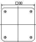
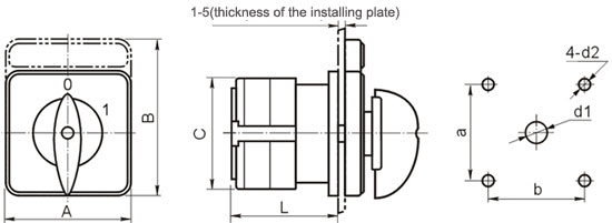
Dimensions and installation
Description | Escutcheon plate | Dimensions (mm) | Installation (mm) |
A | B | C | L | a | b | d1 | d2 |
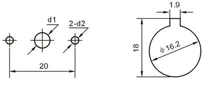
LW26-10 | M0 square | 30 | 30 | 28 | 26.5+12n | 20 | | Φ8 | Φ3.2 |
LW26-20 | M1 square | 48 | 48 | 43 | 22+9.6n | 36 | 36 | Φ8.5 | Φ4.5 |
LW26-25 | M1 square with rectangle plate added | 48 | 60 | 43 | 22+9.6n | 36 | 36 | Φ8.5 | Φ4.5 |
M2 square | 64 | 64 | 43 | 25+9.6n | 48 | 48 | Φ10 | Φ4.5 |
M2 square with rectangle plate added | 64 | 80 | 43 | 25+9.6n | 48 | 48 | Φ10 | Φ4.5 |
M1 square | 48 | 48 | 45.2 | 23+12.8n | 36 | 36 | Φ8.5 | Φ4.5 |
LW26-32 | M1 square with rectangle plate added | 48 | 60 | 45.2 | 23+12.8n | 36 | 36 | Φ8.5 | Φ4.5 |
M2 square | 64 | 64 | 45.2 | 26.5+12.8n | 48 | 48 | Φ10 | Φ4.5 |
M2 square with rectangle plate added | 64 | 80 | 45.2 | 26.5+12.8n | 48 | 48 | Φ10 | Φ4.5 |
LW26-63 | M2 square | 64 | 64 | 58 | 29.2+12.8n | 48 | 48 | Φ10 | Φ4.5 |
M2 square with rectangle plate added | 64 | 80 | 58 | 29.2+12.8n | 48 | 48 | Φ10 | Φ4.5 |
M2 square | 64 | 64 | 66 | 29.2+21.5n | 48 | 48 | Φ10 | Φ4.5 |
M2 square with rectangle plate added | 64 | 80 | 66 | 29.2+21.5n | 48 | 48 | Φ10 | Φ4.5 |
LW26-125 | M3 square | 88 | 88 | 66 | 29.2+21.5n | 68 | 68 | Φ10 | Φ4.5 |
M3 square with rectangle plate added | 88 | 107 | 66 | 29.2+21.5n | 68 | 68 | Φ10 | Φ4.5 |
M3 square | 88 | 88 | 84 | 35+26.5n | 68 | 68 | Φ13 | Φ |
LW26-160 | M3 square with rectangle plate added | 88 | 107 | 84 | 35+26.5n | 68 | 68 | Φ13 | Φ6 |
M3 square | 88 | 88 | 88 | 35+32.5n | 68 | 68 | Φ13 | Φ6 |
M3 square with rectangle plate added | 88 | 107 | 88 | 35+32.5n | 68 | 68 | Φ13 | Φ6 |

LW26-20 Round escutcheon plate

LW26-10 front installation、hole installation


 M0
M0 R type
 I type
 M1
M1 F type
 B type
 M2
M2 S type
 L type
 M3
M3 P type
 K type


